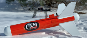
UAV VLF-EM SYSTEM: Resistivity Mapping Solution
VLF Theory
The Very Low-Frequency (VLF) Electromagnetic Method (EM) survey technique is a passive method that utilizes distant, globally positioned transmitters that are broadcasting at frequencies in the range of 15.0 – 30.0kHz. In a VLF investigation the primary fields (generated by the radio transmitters) are horizontal, vertical deviations are measured (which are effected by local ground conditions).
Applications may include;
• Exploration for mineralized bodies
• Resistivity imaging for bedrock mapping
• Delineate contrasts in conductivity at depth • Map geological contacts (i.e. faults)
• Water exploration
• Detection of underground pipelines
Surveying with UAVs and Drones
Revolutionary, Unmanned Aerial Vehicles (UAVs) can be used to perform airborne geophysical surveys. Acquiring data via drone offers many advantages such as time efficiency, being cost effective, as well as the opportunity to survey in areas that are not easily accessible (i.e. swamps) when compared to traditional manned-aircraft or ground surveys. In addition, UAV-borne VLF surveys can deliver better data quality in environments where topography and safety standards prohibit manned aircrafts from acquiring data at optimum terrain clearances.
Technically Superior
GEM Systems GSM-90AVU UAV VLF system provides true measurements of the Vertical in- phase & Out-of-phase components as % of total field within the VLF frequency range of 15.0 – 30.0kHz. Many older systems only measure the total field and quadrature components of the field. This VLF system features two separate sensors with three light weight orthogonal air coils in each to provide reduced noise and allow true in-phase and quadrature data to be gathered rapidly from two VLF transmitting stations simultaneously, regardless of sensor orientation. Data includes in-phase, out-of-phase, horizontal components in x and y and field strength in picoTesla (pT).
The GSM UAV-VLF System includes:
- Two (2) VLF UAV Sensor coils with cables
- GSM-90AVU v7.0 VLF Electronics
- UAV VLF shell with 10m tow line
- Laser altimeter
- GPS (1.5m L1, 0.6m SBAS resolution)
- Radio Link (base station and remote)
- Ground station computer and GEM Airborne logger software (GEMDAS Data acquisition)
UAV-VLF Specifications
- VLF Frequency: Two (2) user selected stations in the frequency range of 15.0 – 30.0kHz (simultaneous measurements).
- Parameters: Vertical in-phase and out-of-phase (quadrature) components as % of total field. • 2 components of horizontal field amplitude and total field strength in pT.
- Resolution: 0.1% of total field (VLF fields >5 pT)
- Tilt Correction: +/- 10 degrees (off horizontal)
- Performance: 10, 5, 2, 1 Hz (Sample Rate)
- Operating Temperature : -40°C to +50°C
- Dimensions: Sensor : 14 x 15 x 11 cm. (5.5 x 6 x 5 inches), Console: 22.3 x 6.9cm x 2.4 cm
- Weights: Sensors : 0.65 kg (1.43 lb.), Electronics : 1.21 kg (2.66 lb.), Towed Bird : 4.4 kg (9.68 lb.)
- Power Source: 11.1V 1.3Ah Lithium Battery
- Outputs: UTC time, GPS Position (latitude, longitude), altitude, pitch, roll, yaw, EM field, frequency, in- and out-of-phase vertical, and both horizontal components for each selected station. Data export in standard XYZ (i.e. line-oriented) format for easy use in standard commercial software programs such as VLF2DMF by EMTOMO (Optional).

REQUEST A CALLBACK
If you would like to receive a callback from GEM Systems.

NEWS and EVENTS


